- 您现在的位置:买卖IC网 > Sheet目录1219 > HC5514XEVAL3 (Intersil)EVAL BOARD TI CODEC MOTHER BOARD
�� �
�
�Application� Note� 9871�
�0�
�-5�
�-10�
�-15�
�-20�
�-25�
�-30�
�-35�
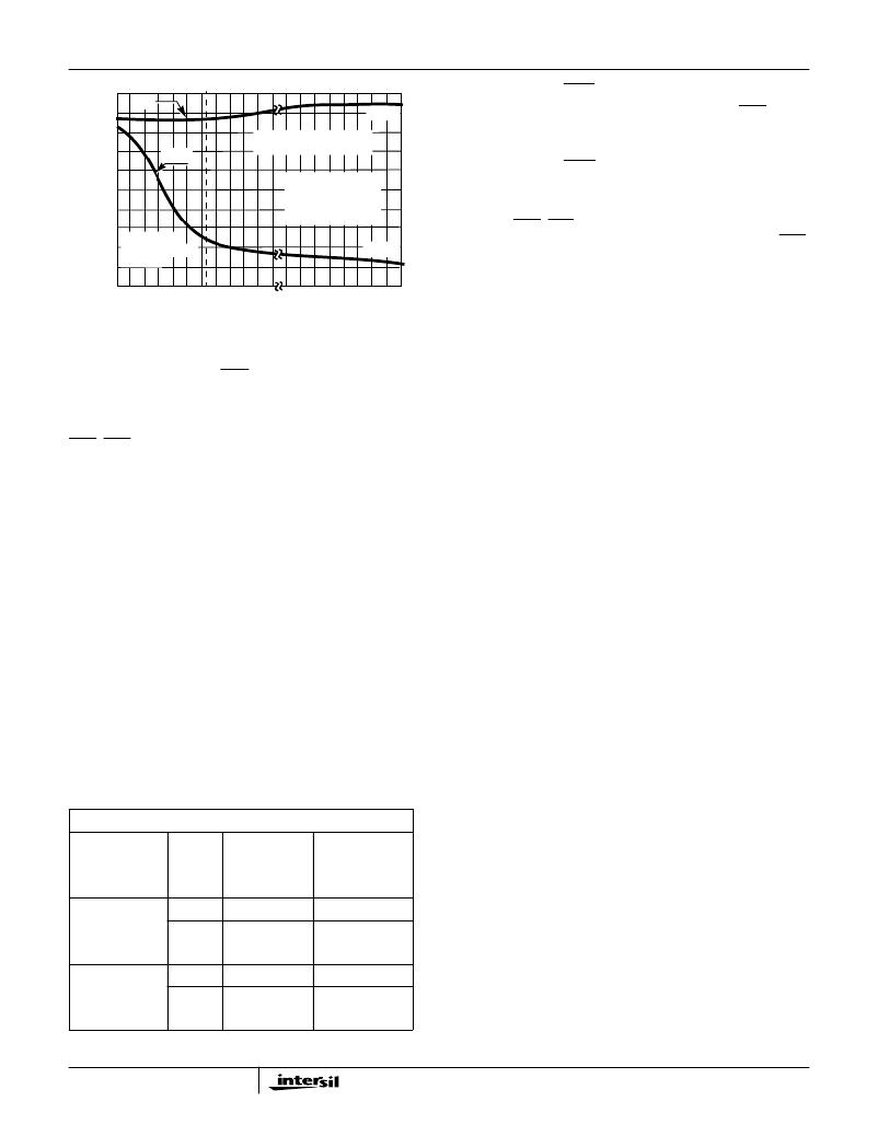
�TIP�
�RING�
�-2.5V�
�CONSTANT� TIP� TO� RING�
�VOLTAGE� REGION�
�VBH� =� -48V�
�RD� =� 41.2k� ?�
�ROH� =� 38.3k� ?�
�RDC_RAC� =� 19.6k� ?�
�RILim� =� 33.2k� ?�
�Veri?cation� of� SHD:�
�1.� With� the� SLIC� in� the� forward� active� state,� the� SHD� LED� is�
�on� when� tip� and� ring� are� terminated� with� 600� ?� and� off�
�when� tip� and� ring� are� an� open� circuit.�
�Veri?cation� of� GKD:�
�1.� Con?gure� the� SLIC� to� be� in� the� Tip� Open� State�
�(C3� =� 1,� C2� =� 0,� C1� =� 0).�
�2.� The� GKD_LVM� LED� is� on� when� ring� is� shorted� to� ground�
�-40�
�-45�
�CONSTANT�
�LOOP� CURRENT�
�REGION�
�-44.5V�
�and� off� when� ring� is� an� open� circuit.� Notice� that� the� SHD�
�LED� will� also� be� on.�
�-50�
�200�
�600� 1000� 1400� 1800� 2000�
�4K�
�6K�
�8K�
�10K�
�Test� #3,� Gain� Veri?cation�
�LOOP� RESISTANCE� (� ?� )�
�This� test� will� verify� the� SLIC� is� operating� properly� and� that�
�A� 4-2� =� -----------� =� -2� -------------------------� =� –� 2� ----------------------------------------------�
�Z� L� +� ?� ----------� +� 2R� P� ?�
�FIGURE� 2.� TIP� AND� RING� VOLTAGES� vs� LOOP� RESISTANCE�
�The� Ground� Key� detector� (GKD)� operation� is� veri?ed� by�
�con?guring� the� HC5514X� in� the� tip� open� state� and� grounding�
�the� 4-wire� to� 2-wire� gain� (Equation� 1)� is� -1.0� (0.0dB).�
�V� TR� Z� L� Z� L�
�V� RX� Z� L� +� Z� TR� Z� T�
�?� 200� ?�
�(EQ.� 1)�
�the� ring� pin.� Grounding� the� ring� pin� results� in� a� current� that�
�triggers� an� internal� detector� that� pulls� the� output� of�
�GKD_LVM� low,� illuminating� the� LED� through� the� +5V� supply.�
�Setup� (Tip� and� Ring� Voltages)�
�The� programmable� 2-wire� to� 4-wire� transmission� gain�
�(Equation� 2)� will� also� be� veri?ed� by� measuring� the� SLIC’s� 4-�
�wire� to� 4-wire� gain� with� the� PTG� pin� ?oating� (A� 2-4� is� 0.9�
�(0.91dB)� and� grounded� (A� 2-4� is� 0.56� (-5.0dB).)�
�A� 2-4� =� -----------� =� -----------------------------�
�1.� Connect� the� power� supplies� to� the� Evaluation� board.�
�2.� Set� V� BH� to� -48V,� V� BL� to� -24V� and� V� CC� to� +5V.�
�3.� Con?gure� the� SLIC� to� be� in� the� Forward� Active� State�
�V� TX� Z� TR� -� 2R� P�
�V� TR� Z� TR�
�(EQ.� 2)�
�(C3� =� 0,� C2� =� 1,� C1� =� 0).�
�4.� Verify� that� the� POL/REV� pin� (lower� right� hand� side� of� the�
�board)� is� in� either� the� 10ms� or� 20ms� position.�
�5.� Con?gure� S5� and� S6� switches� to� be� in� the� LED� position.�
�6.� Disconnect� any� loads� from� across� tip� and� ring.�
�7.� Measure� tip� and� ring� voltages� with� respect� to� ground� and�
�compare� to� those� in� Table� 2� (onhook).�
�8.� Terminate� tip� and� ring� with� a� 600� ?� load.�
�9.� Measure� tip� and� ring� voltages� with� respect� to� ground� and�
�compare� to� those� in� Table� 2� (600� ?� ).�
�10.� Con?gure� the� SLIC� to� be� in� the� Reverse� Active� State�
�(C3� =� 1,� C2� =� 1,� C1� =� 0).�
�11.� Repeat� steps� 6� through� 9.�
�Discussion�
�When� tip� and� ring� are� terminated� with� 600� ?� load,� the� SLIC�
�will� exhibit� unity� gain� from� the� 4-wire� VRX� input� pin� to� across�
�the� 2-wire� tip� and� ring� pins� (V� TR� ).� The� dB� gain� is� calculated�
�in� Equation� 3.� When� an� open� circuit� exists,� a� mismatch�
�occurs� and� the� tip� to� ring� voltage� doubles.�
�An� easy� way� to� measure� the� 2-wire� to� 4-wire� transmit� gain,�
�without� a� ?oating� signal� generator� on� the� 2-wire� side,� is� to�
�measure� the� 4-wire� to� 4-wire� gain.� This� way� the� source� can�
�be� applied� on� the� ground� referenced� 4-wire� side� to� the� VRX�
�pin.� Given� that� the� 4-wire� to� 2-wire� gain� is� approximately�
�one,� it� follows� that� the� 2-wire� to� 4-wire� transmission� gain� is�
�also� approximately� equal� to� the� 4-wire� to� 4-wire� gain.� The� dB�
�4w� to� 4w� gain� is� calculated� in� Equation� 4.�
�dB� 4W� –� 2W� =� 20� log� -----------�
�TABLE� 2.� TIP� AND� RING� VOLTAGES�
�HC5514X�
�TIP�
�RING�
�V� TR�
�V� RX�
�(EQ.� 3)�
�dB� 4W� –� 4W� =� 20� log� -----------�
�LOGIC� STATE�
�R� L�
�(� ?� )�
�VOLTAGE�
�REFERENCE�
�D� TO� GND�
�VOLTAGE�
�REFERENCED�
�TO� GND�
�V� TX�
�V� RX�
�(EQ.� 4)�
�Forward� Active�
�V� BH� =� -48V�
�V� BL� =� -24V�
�V� CC� =� +5V�
�Reverse� Active�
�V� BH� =� -48V�
�V� BL� =� -24V�
�V� CC� =� +5V�
�Onhook�
�Offhook�
�600�
�Onhook�
�Offhook�
�600�
�-2.6�
�-6.3�
�-44.6�
�-24.4�
�-44.6�
�-24.5�
�-2.5�
�-6.3�
�Setup� (4-Wire� to� 2-Wire� Gain)�
�1.� Connect� the� power� supplies� to� the� Evaluation� board.�
�2.� Set� V� BH� to� -48V,� V� BL� to� -24V� and� V� CC� to� +5V.�
�3.� Con?gure� the� SLIC� to� be� in� the� Forward� Active� State�
�(C3� =� 0,� C2� =� 1,� C1� =� 0).�
�4.� Verify� that� the� POL/REV� pin� S4� (lower� right� hand� side� of�
�the� board)� is� in� either� the� 10ms� or� 20ms� position.�
�5.� Terminate� tip� and� ring� with� a� 600� ?� load.�
�3�
�发布紧急采购,3分钟左右您将得到回复。
相关PDF资料
HC55185EVAL2
EVALUATION PLATFORM HC55185+T
HE1015
BOOT CIRCUIT BREAKER 1POLE CLEAR
HE1020
BOOT CIRCUIT BREAKER 2POLE CLEAR
HE1050
BOOT CIRCUIT BREAKER 3POLE CLEAR
HE1070
BOOT CIRCUIT BREAKER 3POLE CLEAR
HFW30R-1STE1
HFW30R-1STE1-FFC/FPC CONN
HFW30S-2STE1
HFW30S-2STE1-USING HFW-P5SL
HHG
FUSEHOLDER AUTO INLINE FOR ATC
相关代理商/技术参数
HC5515
制造商:INTERSIL 制造商全称:Intersil Corporation 功能描述:ITU CO/PABX SLIC with Low Power Standby
HC5515_06
制造商:INTERSIL 制造商全称:Intersil Corporation 功能描述:ITU CO/PABX SLIC with Low Power Standby
HC55150
制造商:INTERSIL 制造商全称:Intersil Corporation 功能描述:Low Power Universal SLIC Family
HC55150CB
制造商:Rochester Electronics LLC 功能描述:LOW PWR SLIC,POL REV/METERING,55DB BALANCE - Bulk
HC55150CBZ
功能描述:电信线路管理 IC LW PWR SLIC POLV/MTRING 55DB RoHS:否 制造商:STMicroelectronics 产品:PHY 接口类型:UART 电源电压-最大:18 V 电源电压-最小:8 V 电源电流:30 mA 最大工作温度:+ 85 C 最小工作温度:- 40 C 安装风格:SMD/SMT 封装 / 箱体:VFQFPN-48 封装:Tray
HC55150CM
制造商:Rochester Electronics LLC 功能描述:LOW PWR SLIC,POL REV/METERING,55DB BALANCE - Bulk
HC55150CMZ
功能描述:电信线路管理 IC LW PWR SLIC POLV/MTRING 55DB RoHS:否 制造商:STMicroelectronics 产品:PHY 接口类型:UART 电源电压-最大:18 V 电源电压-最小:8 V 电源电流:30 mA 最大工作温度:+ 85 C 最小工作温度:- 40 C 安装风格:SMD/SMT 封装 / 箱体:VFQFPN-48 封装:Tray
HC55151
制造商:INTERSIL 制造商全称:Intersil Corporation 功能描述:Low Power Universal SLIC Family